Selecting Output Capacitor for Buck Converters: Ripple Current Edition


Were you fooled by the post picture? Surprise! This is a circuits post. This beautiful sunset is just to give you a taste of the beautiful derivation that is to come...
How often have you been in this situation? You've found yourself the perfect buck converter for motherboard and you're paging through the datasheet to refresh yourself on inductor and output capacitor selection. You find the equation for selecting the output capacitor - some weird combination of current, frequency, and constants and you wonder to yourself - where did this equation come from? Well, wonder no more! Here's a simple derivation of the formula for output cap selection.
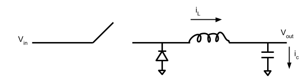
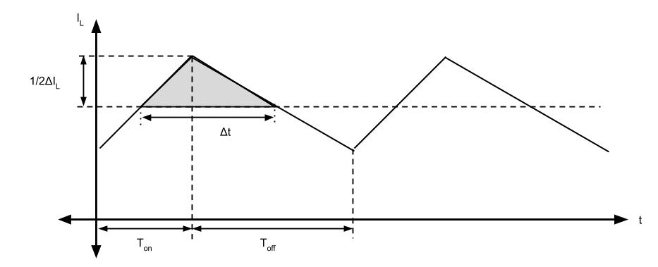
Before we get started on the derivation, let's discuss a few buck converter basics. The diagram below shows the current going through the inductor (\(I_{L}\)). The horizontal dashed line represents the load current (\(I_{out}\)) while the current deviation above and below this line is the ripple current. If you assume a constant \(I_{out}\), the ripple current in the cap (\(I_{C}\)) is equal to the ripple current in the inductor. Therefore, for a buck converter, the output capacitor requirements are determined by (1) how much voltage deviation can be tolerated on the output and (2) how large the ripple current is.
We can define the current in the cap as:
\(I_{C} = C\frac{dV}{dt}\)
\(I_{C}\cdot dt = C\cdot dV\)
Substitution of \(Q=CV\) yields
\(I_{C}\cdot dt = C\cdot dV = dQ\)
\(dQ\) represents the change in charge in the cap, which is also given by the shaded area in the graph. Using the graph and the formula for a triangle, we can also represent the shaded area as:
\(\Delta Q = \frac{1}{2}(\frac{1}{2}\Delta I_{L})(\Delta t)\)
Since the average voltage of the output capacitors is constant, we can assume that the charge going into the capacitors is the same as the charge leaving the capacitors as the converter switches. Therefore, we can rewrite \(\Delta t\) as:
\(\Delta t = \frac{1}{2}T_{on} + \frac{1}{2}T_{off}\)
\(\Delta t = \frac{1}{2}\frac{D}{fs} + \frac{1}{2}\frac{(1-D)}{fs}\)
\(\Delta t = \frac{1}{2fs}\) *
If we substitute this into our equation for charge from above, we get:
\(\Delta Q = \frac{1}{2}(\frac{1}{2}\Delta I_{L})(\frac{1}{2fs})\)
\(\Delta Q = \frac{\Delta I_{L}}{8fs}\)
As we mentioned above, \(\Delta Q\) or the change in charge each cycle and the allowed peak-to-peak voltage ripple \(V_{pp}\) determines the minimum output capacitance \(C_{min}\) that's required to sustain this ripple. Therefore \(\Delta Q = C_{min}V_{pp}\). Substituting this into the above equation, we get:
\(C_{min}V_{pp} = \frac{\Delta I_{L}}{8fs}\)
or
\(C_{min} = \frac{\Delta I_{L}}{8fsV_{pp}}\)
And there you have it! That's the minimum capacitance required to provide a given peak-to-peak voltage ripple based on ripple current alone during a constant load.
At this point, you might be asking, hey, but what about ESR of the capacitors, you haven't taken that into account. To which I say, that's a story for another blog entry! You also might be saying, woah, constant load, that's a pretty big caveat. What about the over/undershoot voltage you might see during a large output current transient. Fear not, I have a derivation for that too and it will be discussed in my next circuits blog entry :).
* Now that I've gone to all the trouble to write this, I see that based on my original argument about input and output charge being equal, the fact that \(\Delta t = \frac{1}{2fs}\) is pretty obvious. However, I spent a lot of time drawing that graph and writing those equations, so I'm going to leave this part as is.